


How does an electronic speed controller for a brushless DC motor work? And what should you consider when you choose the right one?
-
Automation
-
Health & wellness
-
Life environment
-
Automotive
Dec. 21, 2021
In controlling the rotational speed of a brushless DC (BLDC) motor, there are several methods to apply depending on the issues to be solved. Issues on controlling the speed of the BLDC motor vary with individual application. This article discusses how the speed controllers for brushless DC motors control the rotation speed, their typical methods, advantages, and main applications.
- Basics of brushless DC motor speed control
- Voltage control with feedback is a typical method of controlling speed of DC motors
- Two types in drive voltage control of DC motors
- Issues to be aware of when performing speed control of DC motor
- High-accuracy control methods to address the speed control issues in DC motors
- Choose a brushless DC motor that has proper speed control methods to your issue and application
Basics of brushless DC motor speed control
In a brushless DC motor, the relationship between the applied voltage and the load torque determines the rotational speed. This means that, when using the motor, you can control the rotational speed of the motor by changing the applied voltage.
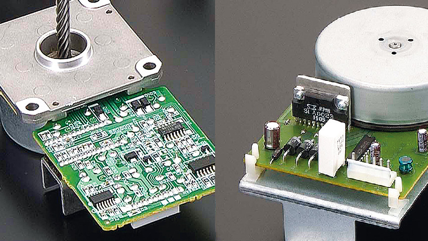
Every brushless DC motor has a drive circuit to rotate the motor, and speed of the brushless DC motor is changed by controlling the drive circuit.
Voltage control with feedback is a typical method of controlling speed of DC motors
The voltage control method is widely used for speed control of DC motors.
Schematically, the voltage control of a DC motor is composed of a motor drive circuit, a controller and a speed sensor. The signal from the speed sensor is fed back to the controller to control the motor speed at or close to the target (reference) speed.
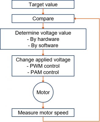 Schematic diagram of DC motor speed control by voltage control
Two types in drive voltage control of DC motors
There are a couple of methods of changing the drive voltage of a DC motor - PWM and PAM.
PWM method
PWM stands for Pulse Width Modulation. This method applies voltage to the DC motor in the form of pulses. By modulating the pulse width (amount of on-duty), the voltage (average voltage) that drives the motor changes.
PWM is implemented with a relatively simple circuit configuration and commonly used in DC motors.
PAM method
PAM stands for Pulse Amplitude Modulation. This method changes the voltage applied to the motor by modulating the voltage level of the pulses.
The PAM method has a more complicated circuit configuration than the PWM method. It is often used in large-size DC motors that are driven by high voltage or DC motors with 100,000 rpm or higher speed, in order to increase the efficiencies of those motors.
Issues to be aware of when performing speed control of DC motors
The challenge when designing a device or product using a DC motor is how close you can reach and maintain against the target speed while the device or product is operating.
Here are examples of the issues for speed control of DC motors.
Changes in load torque
The load torque changes when the load condition or external/internal conditions (temperature, humidity, motor aging) change. These changes will affect the actual speed of the motor.
Residual deviation
Residual deviation is the difference between the target speed and the actual speed, that can occur even when the speed is constantly controlled.
This becomes a problem when the high accuracy in speed is required.
Responsiveness (latency)
The moment of inertia of a motor causes a phase difference in which the rotation speed responds to the drive torque with a delay. When you increase the input voltage to get higher rotational speed, the speed changes with latency due to this characteristic.
This becomes a problem when the actual speed needs to reach the target speed faster.
High-accuracy control methods to address the speed control issues in DC motors
Below are methods for more accurate voltage control, their advantages, considerations and applications. Which method to apply depends on the issue you have to address.
Speed control by hardware
The speed control of DC motors by hardware is implemented on circuit configuration using an IC, and it uses two types of feedback: speed feedback and phase feedback.
The speed feedback applies FG servo or speed discriminator. Both perform feedback control by calculating the difference between the speed measured by the sensor and the target speed.
PLL is a typical phase feedback control method. PLL stands for Phase Locked Loop. It determines the applied voltage by evaluating the phase difference between the pulse signal of the position detected by the sensor and the pulse signal of the target position.
The reason the control by hardware uses both speed feedback and phase feedback is that the residual deviation is still too large with speed feedback alone. Therefore, the phase feedback is incorporated to reduce the residual deviation.
The speed feedback/phase feedback signals are converted to analog voltage by the loop filter, and the voltage is applied to the motor in a PWM or PAM method. The loop filter is also responsible for determining the control characteristics, and the characteristics are adjusted by hardware components that make up the filter circuit such as resistors and capacitors. Therefore, the control characteristics are fixed and must be adjusted in advance properly to the product that uses the motor.
This control method can be used only to applications where the controlled variable is predetermined. Since this method can be implemented at a relatively low cost, it is used on most products on the market, which do not adjust the controlled variable individually.
- Applications
- Devices that perform at a constant speed such as photocopiers, etc.
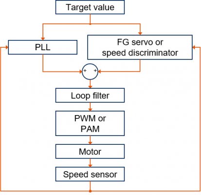 Block diagram of PLL control with FG servo or speed discriminator
Speed control by software
In the speed control by software, the controller configured with a microcomputer performs PID control. PID is an acronym for Proportional, Integral, and Differential. It feeds back the three control elements - the difference between the actual speed and the target speed, its integral and differential. The integral corresponds to the position difference (phase difference) and plays a role in reducing the residual deviation. The differential corresponds to the acceleration difference and works to improve the responsiveness. The use of a microcomputer means that the control characteristics are variable. Therefore, you can adjust them on each individual device that are using the motor.
A motor with this method tends to cost relatively high because it uses a microcomputer. However, in recent years, inexpensive microcomputers have become widely available, and many motors are adopting this method.
- Applications
- Devices that require more parameter adjustments. Robots, etc.
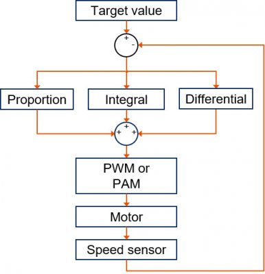 Block diagram of PID control
Choose a brushless DC motor that has proper speed control methods to your issue and application
As discussed, there are a variety of speed control methods for brushless DC motors. Choose a motor with appropriate speed control methods by considering the speed performance requirements (maximum/minimum, changes, accuracy, etc.), loads, ambient conditions and the cost of the motor.
List of the same series columns
- NEMA17 stepper motor selection guide: Mounting dimensions, applications, selection and problem solving
- NEMA stepper motor sizes chart and selection guide
- What does a stepper motor do?
- Applications for blower motor
- What is a blower motor?
- Advantages of brushless DC motors over brushed DC motors
- Features and applications of DC motors
- Is this brushless motor cheap or expensive? - What factors determine its price?
- Different types of DC motor and their respective features
- What is a geared brushless DC motor?
- Small brushless motors
- Difference between brushed motor and brushless motor
- What are the disadvantages of brushless DC motors? And how can they be overcome?
- Advantages of brushless DC motors: How they differ from brushed DC motors
- What is a stepper motor?
- What is an actuator?
- How do brushless DC motors work? The need for a drive circuit explained
- What is an electric motor?
- What is a brushless DC motor?
- Do brushless DC motors require a drive circuit? – Controlling brushless DC motors
- How do brushed DC motors work? The need for regular maintenance explained
- How are stepper motors controlled? - Speed control of stepper motors
- How are DC motors controlled? - Speed control of DC motors
- Brushless DC motor applications: examples that demonstrate their features
- Stepper motor applications: Examples that demonstrate their features
- Motors designed for easy control: How do stepper motors work?
- What are the differences between brushed and brushless DC motors?
- What is a PSC motor
- What is a servo motor?
- What is a blower?
- What is a DC motor? - features and mechanisms

Contact us for more information
- New inquiry
- Prototype
- Upgrade
- Customization
- Your spec
- Literature
- Support
- Others