Product created by radical rethink - wheel unit
-
Automation
-
Delivery robot
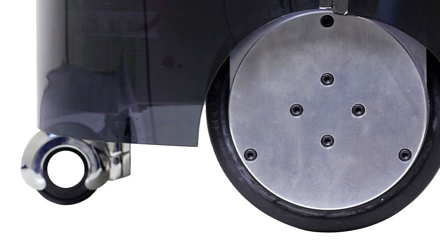
Quest to overturn the conventional approach to wheel units
"I have never before seen such a thin wheel unit!"
This expression of astonishment came from a visitor to the ASPINA booth at a trade show.
"We frequently hear from customers wanting to use our actuators in the wheels of power-assisted trollies or carts. They recognize how integrating the motor and reducer into a small and slim unit represents a step forward for wheel units." This was a comment made by an individual involved in the wheel unit development that commenced in 2017. In response to such requests, we have furthered the development of actuators with slim and lightweight reducers to produce an in-wheel motor which incorporates a motor and reducer into a tire to drive it directly.
Installed on a trolley, in-wheel motors are a reliable way to assist the operation of the trolley or cart undercarriage while keeping its size small. Similarly, installing the battery and control circuits in the space under the trolley where the motor is no longer protruding can reduce the need to locate components on the top side, thereby keeping the overall height of the trolley low. The resulting low center of gravity provides better stability which reduces the risk of accidents such as rollover.
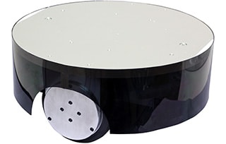 High stability with low center of gravity can be achieved with wheel units installed in a trolly
In-wheel motor created by radical rethink
The initial step in development of the in-wheel motor was to design the fundamental structure of the motor and reducer. Standard practice when using a planetary reducer is to incorporate a power-assist motor into a trolley tire to drive the tire from a shaft located at the center of planetary reducer which has multiple gears. While space is available under the trolley to attach the motor and reducer, this arrangement protrudes out from the tire by the length of the motor and reducer. Moreover, even when using the slim actuators developed by ASPINA, the direct linkage to the tire means that, despite the actuator's slimness, it still protrudes outwards by the amount of its width. Space must also be found on the trolley for the battery and control circuit used to drive the motor. The problem with this conventional configuration is that it makes the trolley larger.
"The reducer configuration we have typically used in the past has a fixed inner gear (an internal gear that has inner-facing teeth) and takes its output from a planetary reducer wheel. However, it should also be possible to reverse this arrangement and build a planetary reducer in which the output is taken from the inner gear. This was a radical rethink to make the reducer slimmer." Instead of driving the wheel shaft from a shaft connected to a planetary reducer, this new idea is to drive the wheel by bringing the inner gear located outside the reducer into contact with the inside of the wheel rim. The successful achievement of such a design would be a major step forward.
Making the reducer slimmer frees up space under the trolley for attaching the battery and control circuit. They also had the idea that this could make power-assisted trollies even slimmer and simpler than before. Many workers would find their jobs easier if provided with trolleys that are safe and have a small turning circle. The in-wheel motor has an important part to play in making this possible.
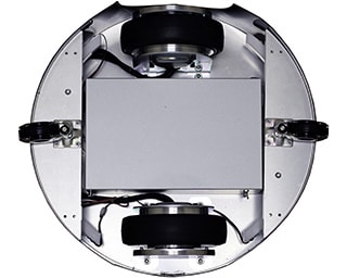 Battery and control circuits can be installed between the wheel units on the underside of a trolly
Having seized on this idea, the in-wheel motor was what resulted from them taking up the challenge.
Technology created by combining know-how from different areas
Unfortunately, there were obstacles with this radical rethink. Having the outer circumference of the reducer rotate meant a larger rotating mass. This has the potential to degrade rotation efficiency and make performance less responsive. In the first place, such a design had not been attempted before. There were numerous obstacles to overcome, such as whether it would work as intended, if strength would be an issue, and what to do about things like material choice, heat treatment, and the accuracy of gear machining. ASPINA made steady progress in development, ticking off these issues one by one.
First, a 3D printer was used to produce a prototype to check the behavior. This confirmed that there were no problems with having the outer circumference rotate. However, this was still only the conceptual testing phase. The next steps were to integrate a brushless motor and reducer into a single in-wheel motor unit. With the work of the departments at ASPINA the idea was turned into a reality by sharing technical know-how and performance analyses that included strength, kinetic efficiency, and precision.
The completed in-wheel motor can be seen as the crystallization of technology brought about by the development teams responsible for reducers, control circuits, and motors. The development team transcended the barriers between their respective departments and fields to combine experience, know-how, and their own personal enthusiasm.
Future uses for in-wheel motor
The hope is that the in-wheel motor will be used in a wide variety of different applications. They should be ideal for the undercarriage of small machinery, such as lightweight service robots or transporters. There are a number of potential new applications of wheel units with a built-in in-wheel motor which are also equipped with interface boards that support different communication protocols. Such interface boards can also be used to drive service robots capable of automatic control by incorporating things like load capacity, speed of travel, range of movement, and behavioral patterns.
 Wheel units can be a vital component of warehouse transporters.
Such products have the potential to become an innovative new form of autonomous control technology for startup companies or research institutions. For example, those who want to build robots that can communicate with people as they move about but are concerned with the challenges of developing the robot undercarriage on their own.
With enhancements to functions such as those that determine position, identify obstacles, and map space, the wheel unit could go on to become a vital technology component for customers that are developing the transportation of the future.
Exhibition information
-
May 19, 2025
-
Dec. 27, 2024


